![]() Cable
Installation
Cable
Installation ![]()
Use The Back Button To Return To the Tech Menu
![]() Cable
Installation
Cable
Installation ![]()
Use The Back Button To Return To the Tech Menu
Installing a cable setup in 1965-66 Mustangs is no easy task. I have completed two of these jobs. One important observation, on the two cars the conversion was conducted on, both were V-8 cars. One had JBA Shorty style headers and the other had Tri-Y’s. The Shorty style headers worked better. They allowed more room in the area where the cable inserts into the bell housing. With the Tri-Y’s you have to make a 90-degree turn upward immediately from the bell housing and fabricate a bracket to keep the cable from making contact with the headers. If you have not purchased headers yet consider the Shorty style.
The first thing to do is install the Borg Warner T-5 transmission. If you have not done this go over to this web site www,themustangshop.com and go to the How to section for the T-5 install.
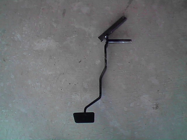
This is great site with pics that explain the change over steps in great detail. All information pertaining to the Z-bar setup can be disregarded. Next remove the fresh air intake duct and drivers seat. This is needed for working room. If you are upgrading from a 3-4 speed remove the clutch pedal. If converting from an automatic, purchase a used clutch pedal. The cross bracket that is used for the clutch stop that is stamped onto the clutch pedal may be remove if desired. The pedal stop that is on the pedal bracket on stick-shift cars must be removed. The new set-up will sit slightly higher. I used a piece of 3/8-angel iron (approx. 5" long) that was welded to the top of the pedal. The metal is welded at approximately a 44-degree angel on top of the clutch pedal facing toward the inside. This will place the point of cable attachment directly above or just to the right of the brake pedal. It is CRITICAL that the point where the cable attaches to the pedal is 2 ½" – 3" above the pivot point. This is needed so the clutch will fully disengage with the 7"-8" of travel you have with the pedal inside the car.
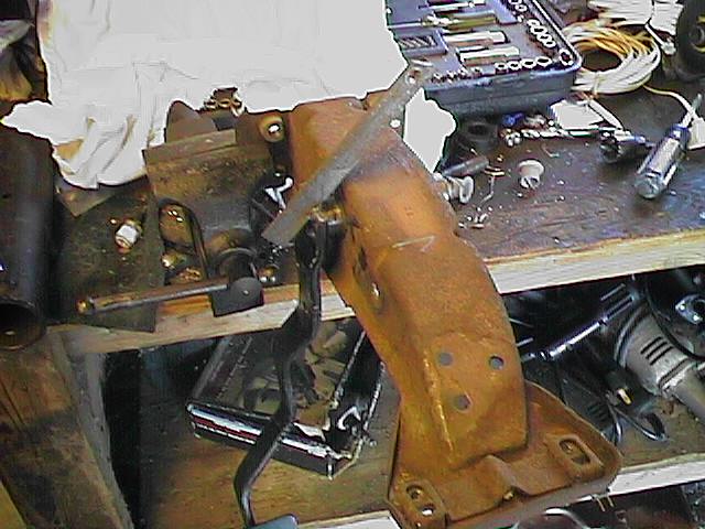
This pic on the left shows the pedal installed in a pedal support (Excuse the mess in my garage). A hole is drilled at the top of the bracket to attach the cable. You will have to install the pedal in the car several times while grinding off the top of the bracket until there is no interference with the cowl. Leave approx. 1/8" clearance. Welding this bracket in this fashion takes advantage of the cowl elevating toward the center of the car. If the pot metal pedal bushings are worn, now is the best time to remove the pedal support and install the steel replacement bushings.

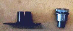
With the limited space under the Mustang dash, I found that an adjuster on the firewall is necessary for cable adjustment. I used the aluminum firewall adjuster from Mustang Parts Specialties at www.stangparts.com order the cable, adjuster & aluminum quadrant. The quadrant will not be used but can be sold to a friend with a Fox body when his plastic one breaks.
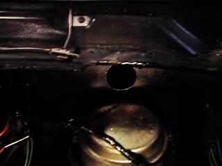
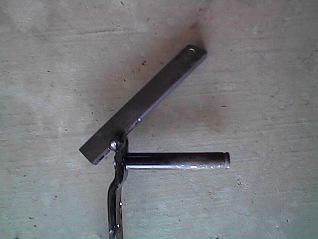
The next step is to drill a ¾" hole in the firewall. The hole in this picture on the left is 1-1/4". I had planned to put the adjuster directly into the hole and use the firewall as the mounting point, but I learned that the inside cowl drops down about 1/2" that prevented the adjuster from fully seating in the cutout/firewall (read, new bracket to build). There is a depression in the firewall area where the brake master cylinder mounts. You will drill the hole in the 1-1/4" space that is available below the cowl seam & above the brake cylinder depression. Drill your hole in the location that best aligns with your bracket. A bracket is then built to mount the adjuster. From a piece of 1/8" X 4-1/2" L X 1-3/4"W flat stock & a 1-1/2" section of 1-1/4" pipe, the pipe is welded, centered onto the flat stock and then the center of the flat stock within the pipe is removed. This will allow cable adjustment from the engine compartment. I drilled & taped a section of the pipe (that would be on the bottom & not seen) & installed an allen screw to hold the adjuster securely in the bracket. This bracket will be attached to the firewall over the 3/4" hole drilled for the cable & attach with two self-taping screws.
If you want me to build one for you, the cost is $20.00 + $5.00 S & H = $25.00. Production pieces look better than this prototype, To order press HERE if you want one.
The clutch cable will need to be modified. Using a high-speed cut-off wheel cut the cable at the top section that attaches to the fox body quadrant. Remove the cable & discard the top hat style connector. Cut the cable sleeve right next to the plastic end mount that inserts into the bell housing. Clean out the pieces of the cable & sleeve that remained in the plastic tip. I used a small screwdriver to do this. Using only the cable sleeve, mount the top part on the firewall and lead the cable down to the bell housing mounting point to get a measurement. With Shorty style headers I lead the cable between the steering box & shock tower to the bell housing. Tri-Y’s, I made a hard 90 degree from the bell housing and on up to the adjuster & fabricated a bracket (zip tie) attached to the steering box to ensure the cable didn't touch the header. After a measurement is made cut the cable sleeve again with the cut-off wheel (Tip: cut the cable sleeve 2-3" longer, you may need it later, easier to shorten cable than it is to grow it). Ensure the cable sleeve interior liner is still round & clear of debris on the end you’ve been cutting on. Insert the now shorter cable sleeve into the plastic tip & into the bell housing & into the adjuster. Next, have the adjuster fully collapsed. Feed the cable from the bottom, attaching it to the clutch fork, and into the dash area. While holding the clutch pedal approximately 2" closer to the driver than the brake pedal, pull the cable taught, mark & remove the cable & trim to the desired length. I used two 3/8" cable clamps found at the hardware store to attach the cable to a piece of 3/8" of all-thread. Using a nut, the all-thread is inserted through the hole in the angel iron and secured. Keep the piece of all thread under 2" long. I tried using this as the only adjustment but found it impossible to make adjustments after the air duct is re-installed & the pedal being depressed several times, deforms the threads to prevent easy adjustment. There are businesses that will crimp a threaded rod onto the cable if you so desire, but I would go through this clamp method first to verify cable length needed. As mentioned the adjuster bracket was built due to the hole that was drilled in the firewall allowed the cowl to interfere with the adjuster. If your hole ends up closer to the center of the car you MIGHT not need this holder but the firewall should still be strengthened with some 14 gauge stock so the firewall does not crack. When attached to the pedal bracket the cable clamps might rub against the cowl. If this happens take a small wooded drift & tap it from the bottom to put a small indention in the cowl for clearance. After all this is done, attach a small lightweight 3 1/2" spring to the hole on the pedal & connect it to the firewall. This will keep slack out of the cable & your foot from pulling the pedal too far forward if you have big feet. Good Luck!!!
If you have questions please contact me.
Contents of this page belong to
Rosehill Performance Parts , copyright 1998-2006, Please link but don't copy.![]()